Modify Connected Splices
This section describes how to modify splice locations and tray locations within a splice enclosure feature.
Swap a Tray’s Location Inside of a Splice Enclosure
- In an existing splice enclosure feature with allocated trays, open the splice enclosure with Connections Manual.
- Select the trays to be swapped by choosing 2 trays (Using the standard Windows Ctrl key to multi select).
- Right click on either of the selected enclosures and choose SWAP TRAYS.
- The trays and all of their connections have now been relocated.

Swap the Contents of Trays
- In an existing splice enclosure feature with allocated splices within trays, open the splice enclosure with Connections Manual.
- Select the trays where the contents are to be swapped by choosing 2 trays (Using the standard Windows Ctrl key to multi select).
- Right click on either of the selected enclosures and choose SWAP CONTENTS.
- The contents of the selected trays have now been swapped.

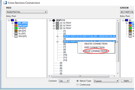
Swap Splice Locations on Trays Within a Splice Enclosure
- In an existing splice enclosure feature with allocated splices within trays, open the splice enclosure with Connections > Manual.
- Expand the trays where the splice contents are to be swapped.
- Choose the splices from each tray, or within a single tray, that are to be swapped.
- Right click on either selected splice, or group of splices and choose SWAP CONNECTIONS.
- The chosen splice connections have now been moved to their new locations.

Edit a Spliced Connection’s Default Loss Value
- In the center window of the Cross Sections Connections dialog box, select a connected fiber for editing.
- Right click on the connection and choose Edit Connection.
- The Edit Splice Pair dialog box appears.
- Apply the known loss for the connection and select OK.
- Select OK in the lower right hand side of the Cross Sections Connections dialog box to apply changes and close the dialog.

Deleting an Existing Fiber Connection
- In the center window of the Cross Sections Connections dialog box, select a connected fiber for disconnection.
- Right click on the existing connection and choose Delete Connection.
- The connection is now deleted, select OK in the lower right hand side of the Cross Sections Connections dialog box to apply changes and close the dialog.
Assign Fiber Entry Ports to Sheaths
- Using Connections > Manual from the Bentley fiber tool bar, select an existing fiber splice enclosure for edit.
- The Cross sections Connections dialog box appears.
- In the empty space located in the center window of the Cross Sections Connections dialog box where the splice name is located, right click and choose Assign Port.
- The Assign Port dialog appears.
- In the Assign Port dialog box, all fiber sheaths associated with the selected splice enclosure will be visible.
- For each sheath, assign the appropriate fiber entry port if known and select OK when finished.
- Select OK in the lower right hand side of the Cross Sections Connections dialog box to apply changes and close the dialog.
